I had a basic version of this posted before, but on my last engine pull decided to update and make it more thorough. I've included almost all (if not all) bolts sizes, and taken crappy cell phone photos along the way. Hopefully this is more helpful!
*Everyone does it different...this is how I do it. This thread isn't going to turn into a pissing match of which way works better, but if you have experience doing something another way, feel free to post up the option*
This particular pull was on a 2000 Cougar 2.5 MTX V6 that was bone stock, It was a returnless fuel system, but I'll try to note the differences if you pulling a return style engine.
The engine in an 01/02 will be returnless like this one, but will have some other slight differences. I'll try to note those as well.
Have a clean garage, organized tools, oil dry, lot's of PB Blaster, three separate containers (for oil, trans fluid, and antifreeze), and a supply of good beer, and this will go quite smoothly.
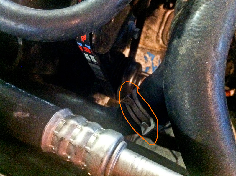
1. Jack up car, support on jackstands (I put them on the subframe, just ahead of the rear subframe bolts. Remove the splash shield from the bumper (f it's still there), and remove the serpentine belt.
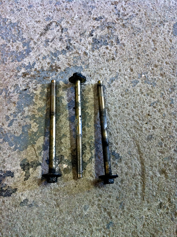
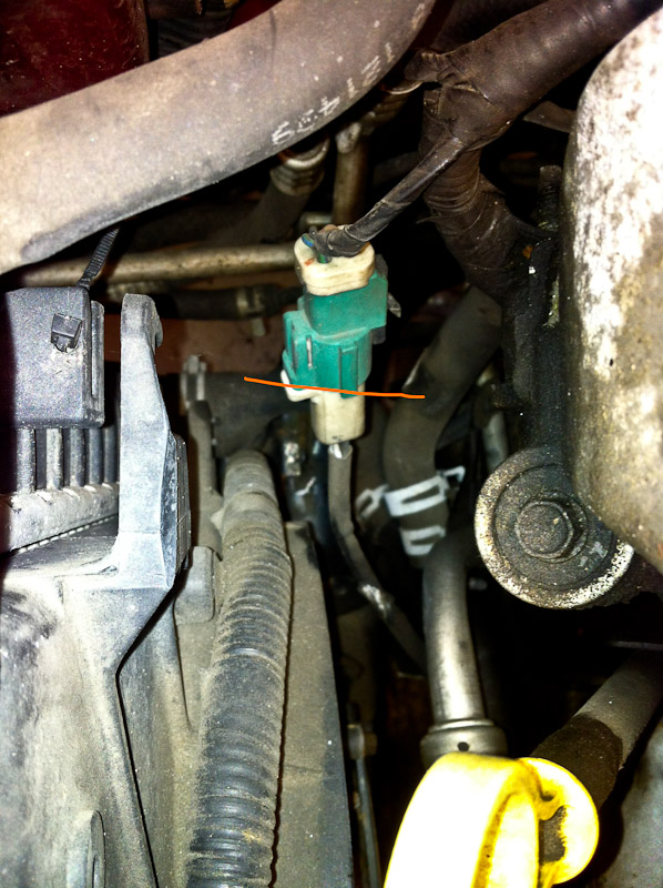
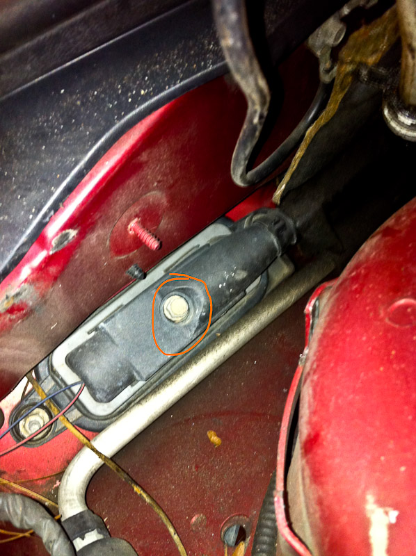
2. Remove the hood – four 10mm bolts, ground is one 8mm, pull washer hose.
![Image]()
![Image]()
![Image]()
3. Drain oil – 15mm
![Image]()
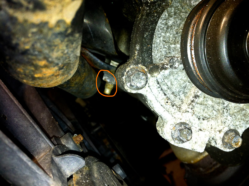
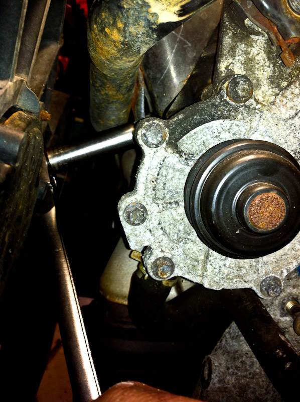
4. Drain trans fluid – 8mm allen
![Image]()
![Image]()
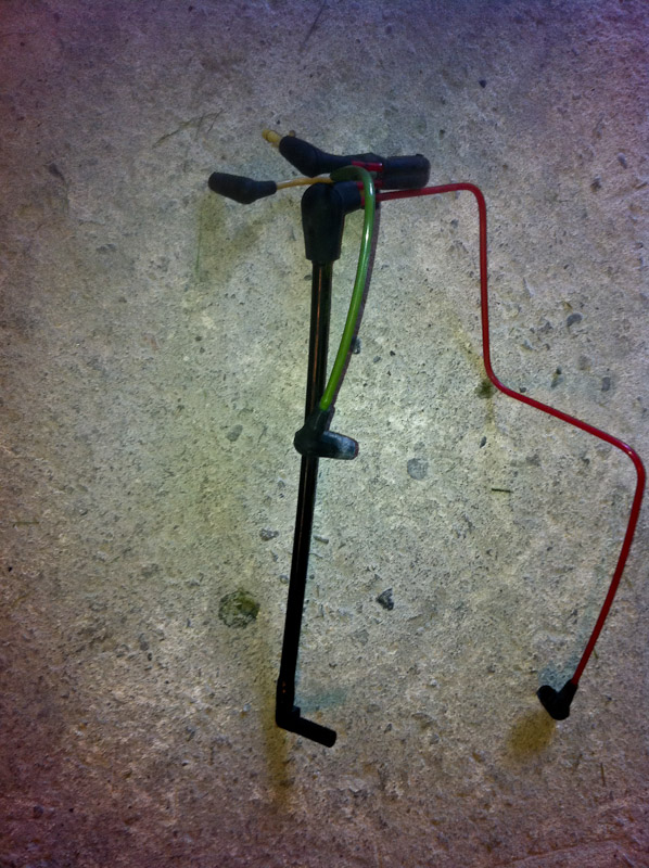
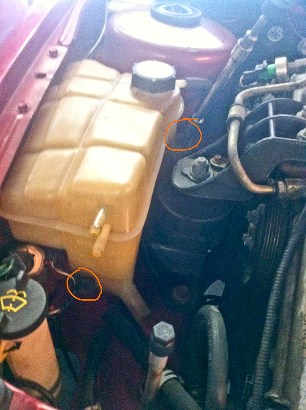
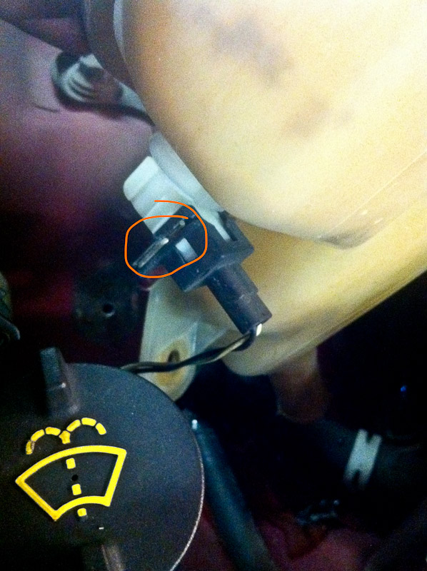
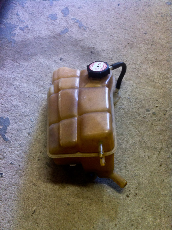
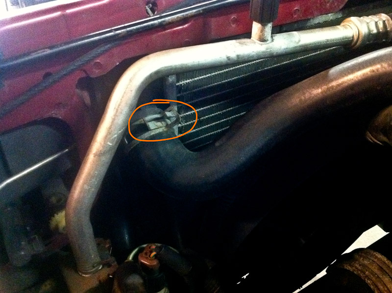
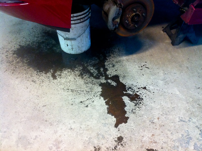
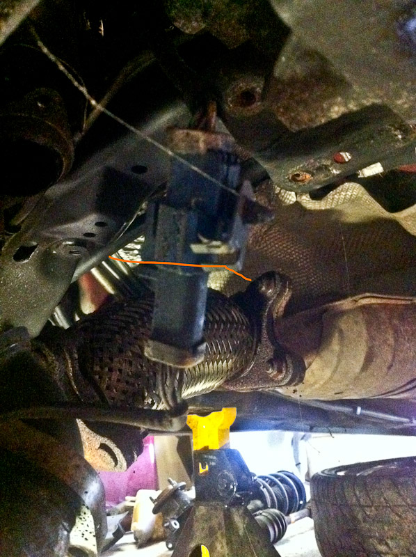
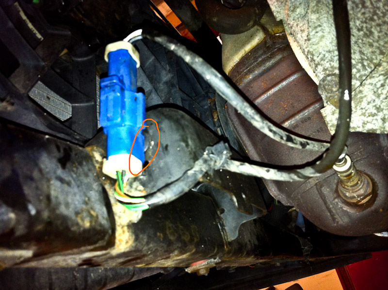
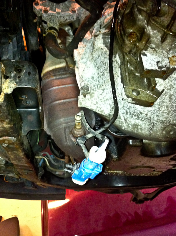
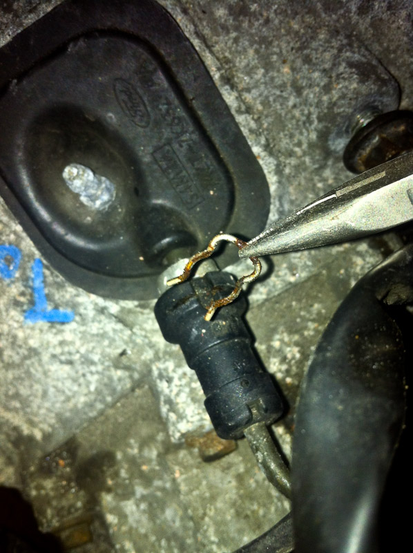
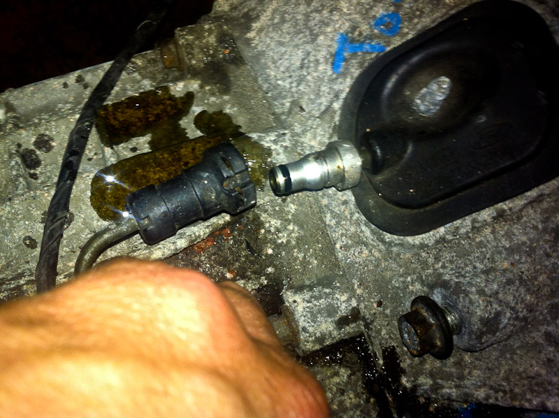
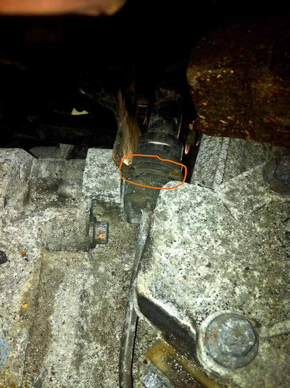
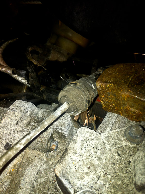
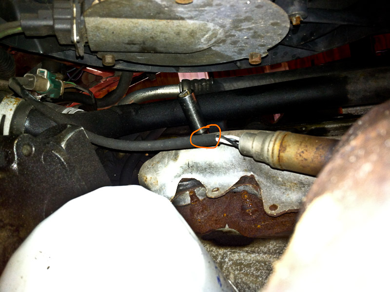
5. Drain coolant – Place a large bucket under the car, use a short flat-head screwdriver. Have some oil dry handy, and of course be careful of animals getting into the antifreeze, as it's poisonous.
![Image]()
![Image]()
![Image]()
![Image]()
![Image]()
![Image]()
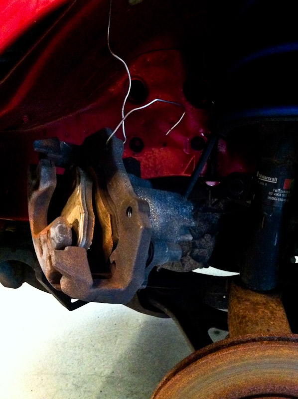
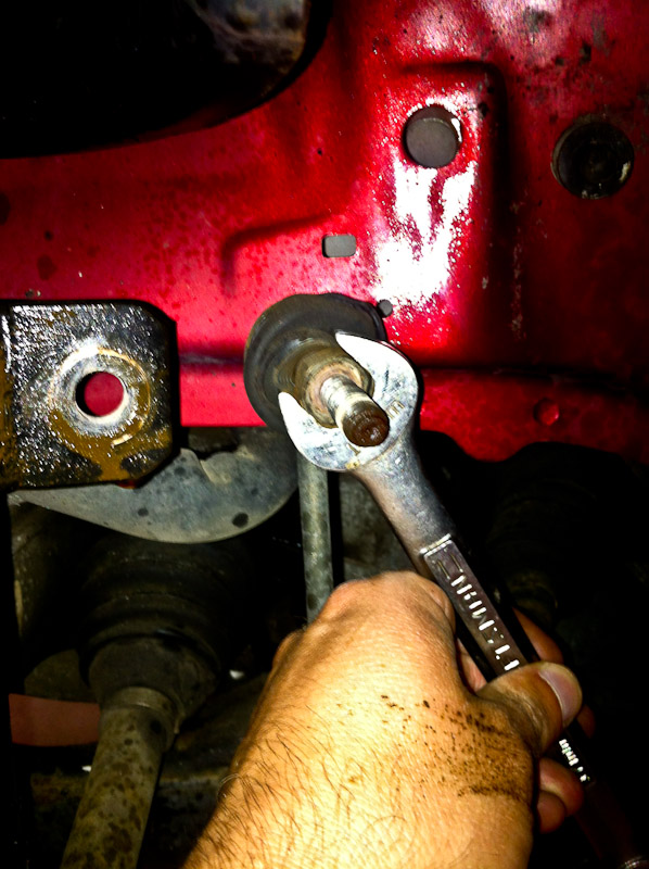
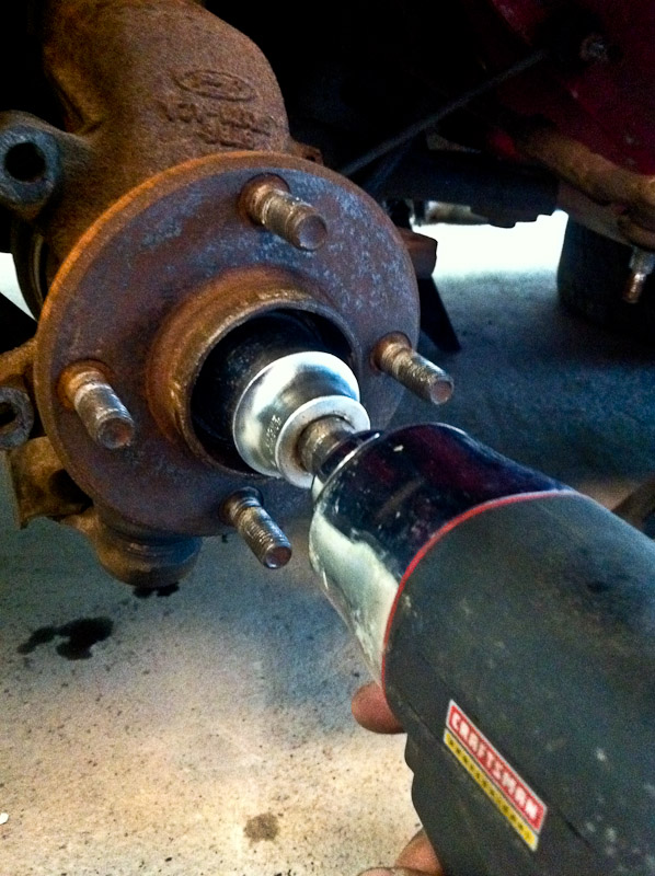
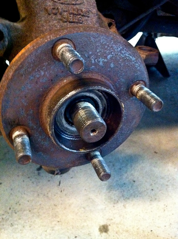
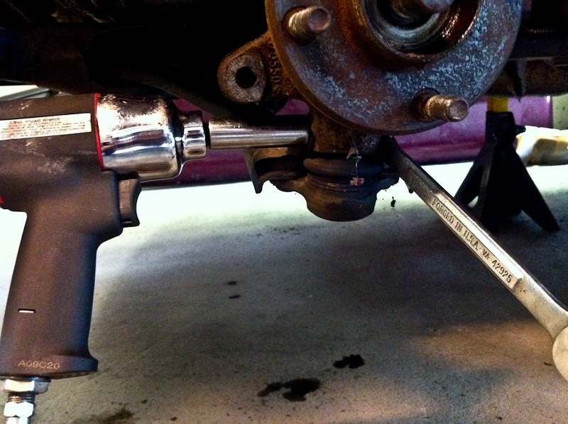
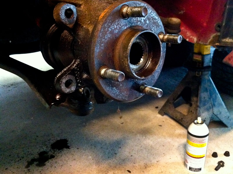
6. Remove front wheels. Place under the car for extra safety.
![Image]()
![Image]()
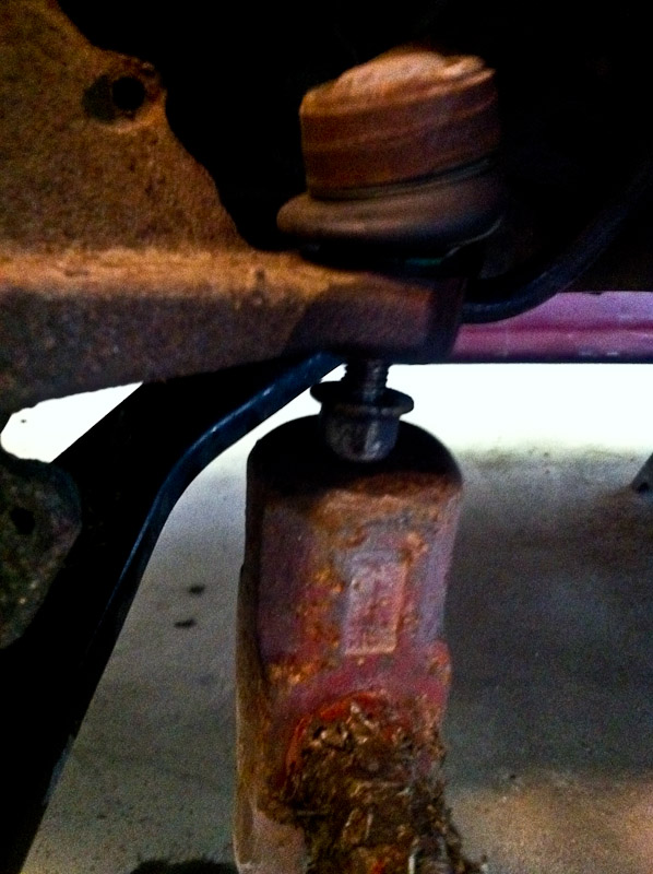
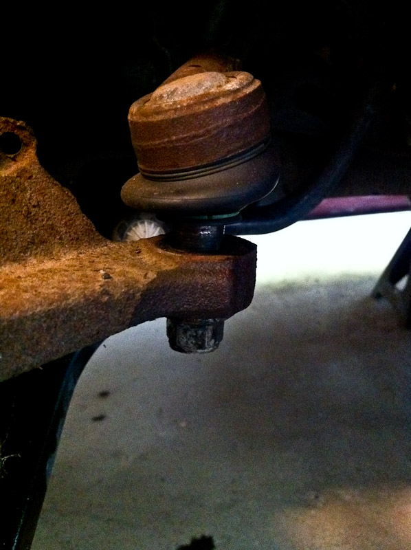
7. Spray PB blaster on y-pipe bolts/engine mounts, suspension bolts.
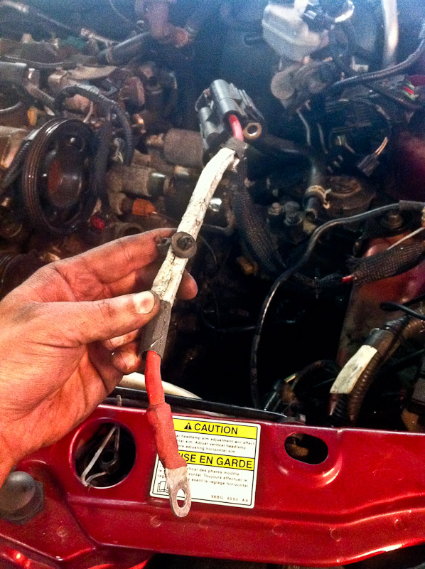
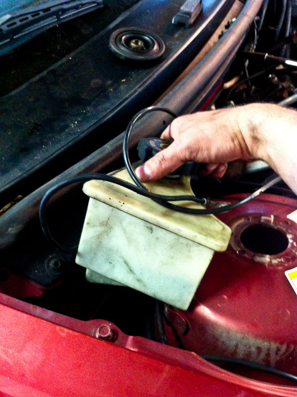
8. Remove battery hold-down - holder two 10mm nuts.
9. Remove battery cables and battery.
![Image]()
![Image]()
10. Remove cover under battery.
![Image]()
11. Spray battery tray bolts with PB Blaster - 7 bolts.
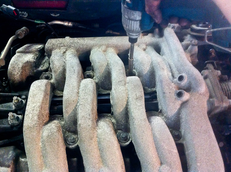
12. Remove Duratec cover - three 7mm bolts.
![Image]()
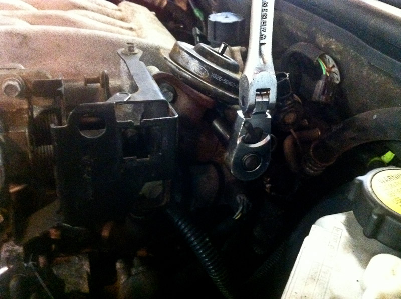
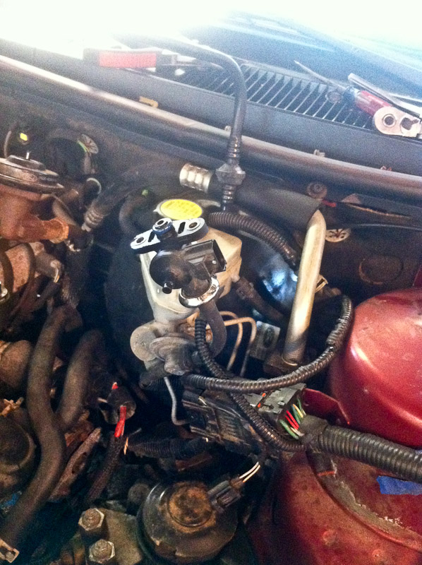
13. Remove IMRC temporarily to access spark plug boots - three 10mm bolts.
![Image]()
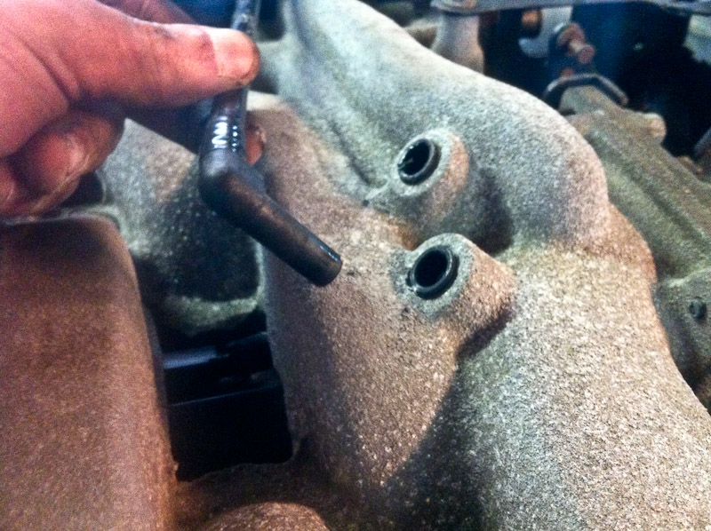
14. Pull out plug wires from front valve cover
![Image]()
15. Replace IMRC.
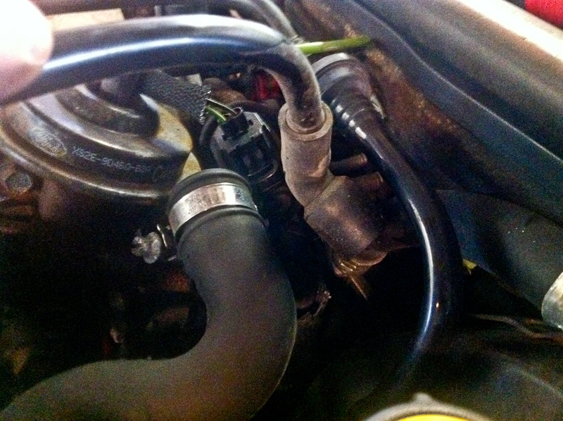
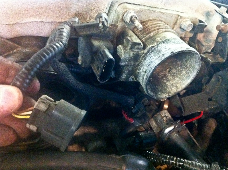
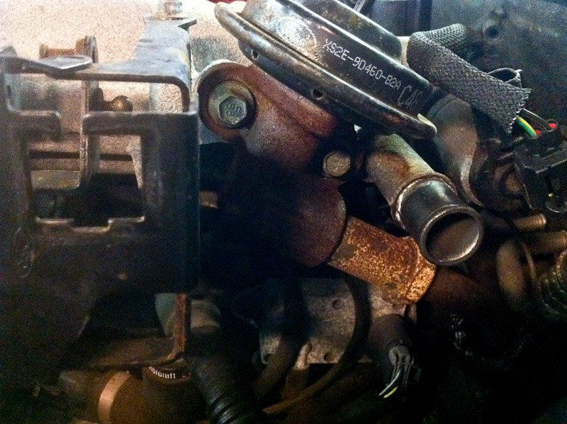
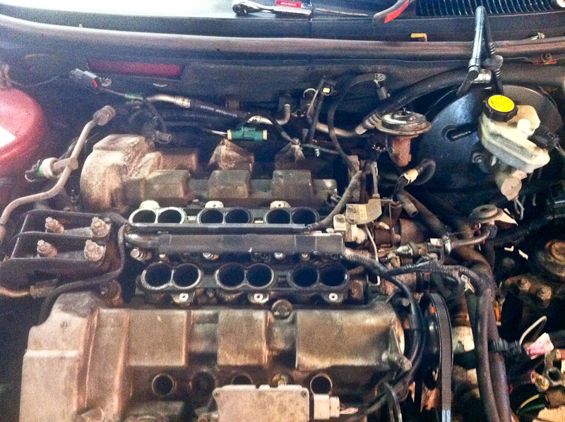
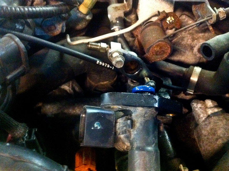
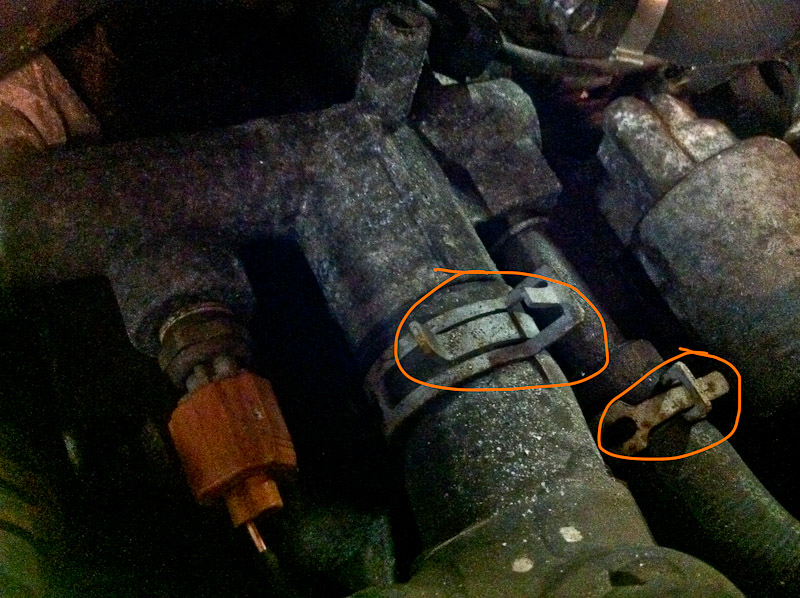
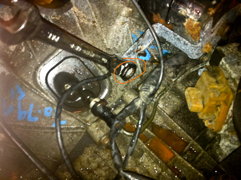
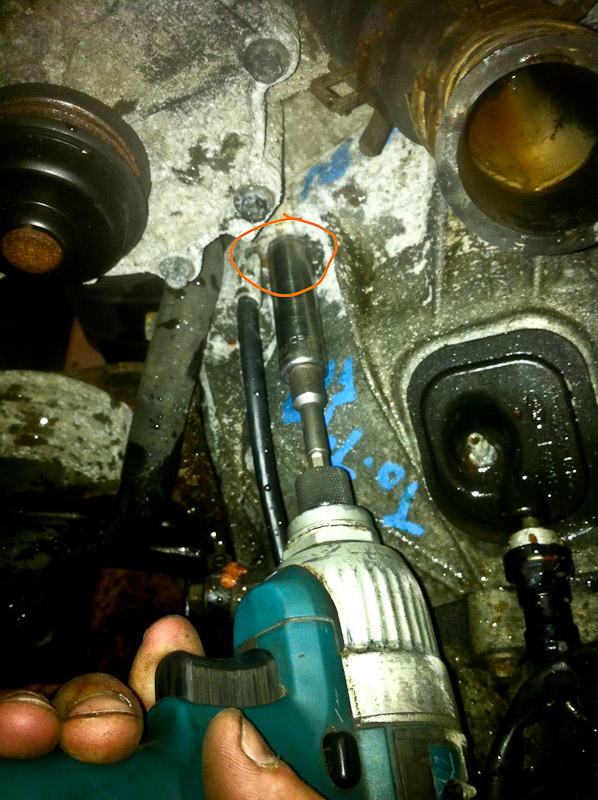
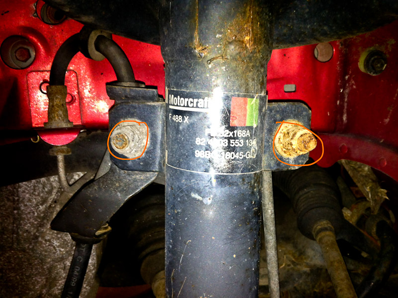
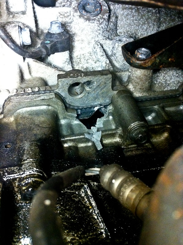
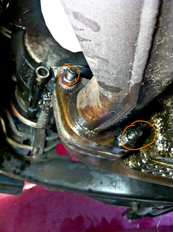
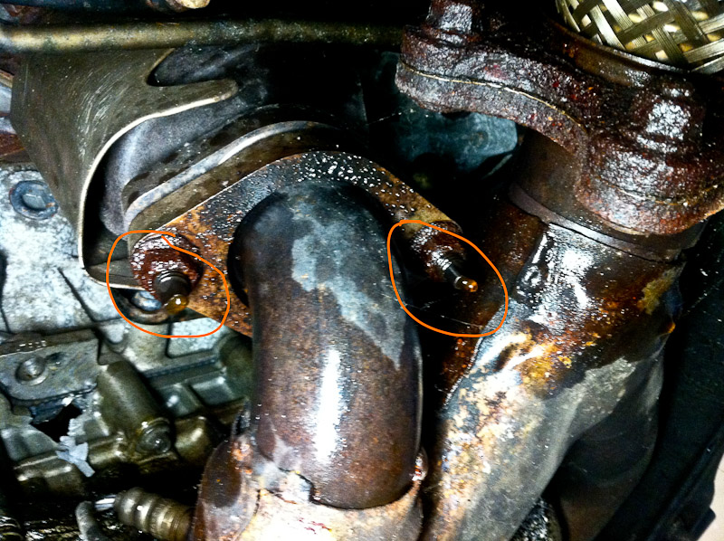
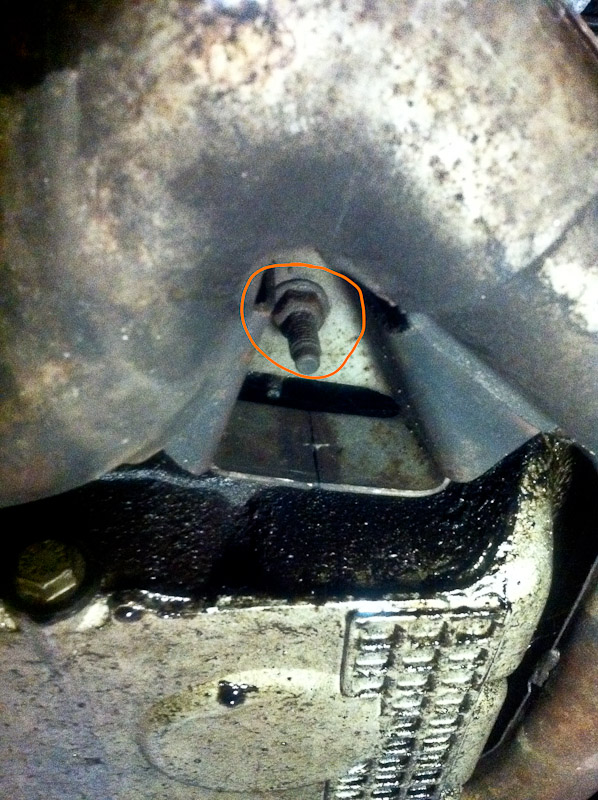
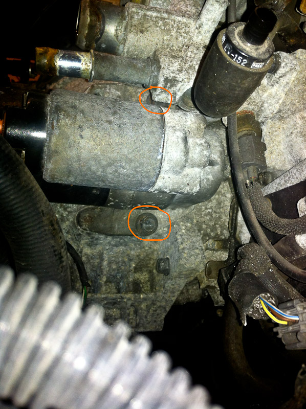
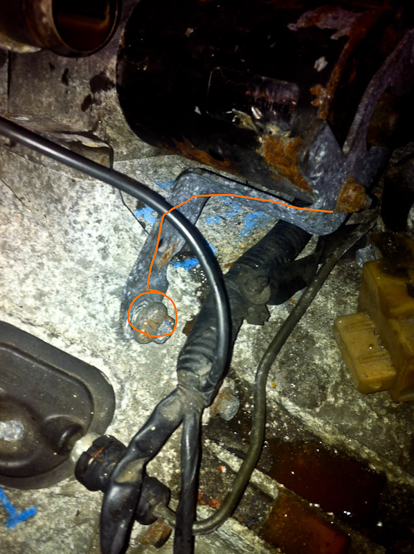
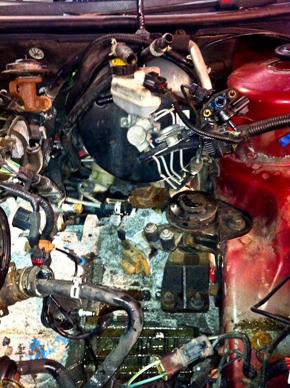
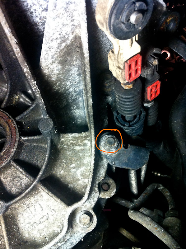
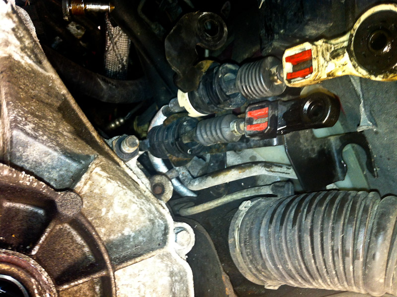
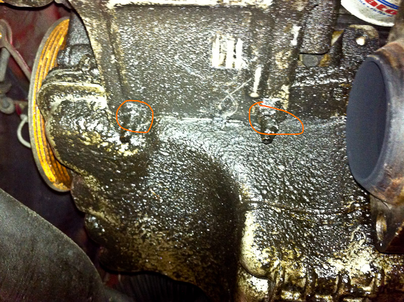
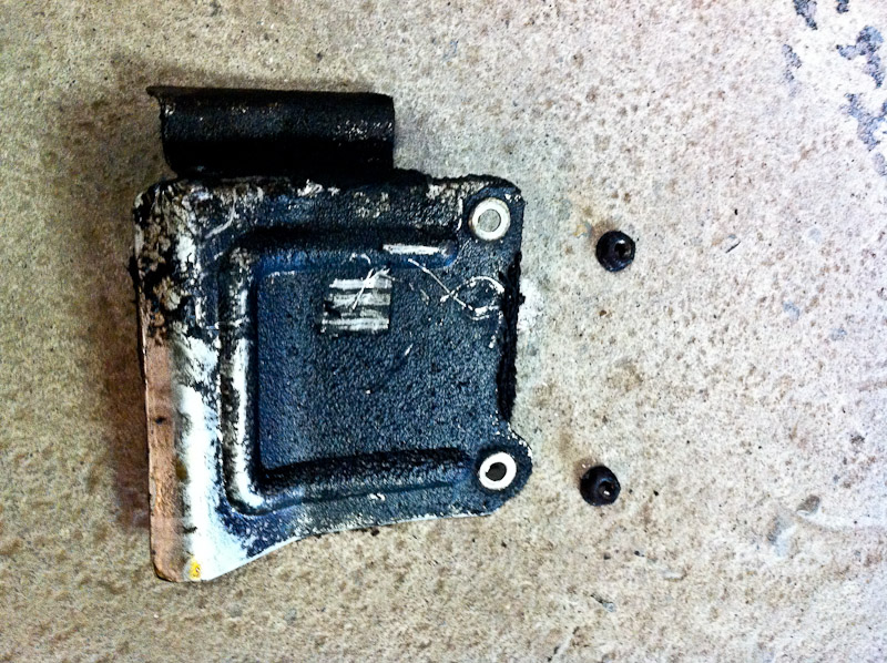
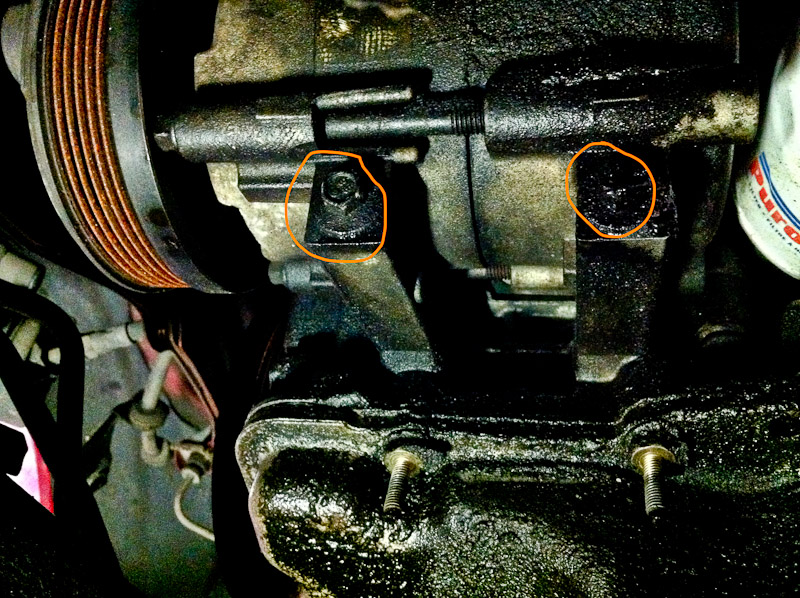
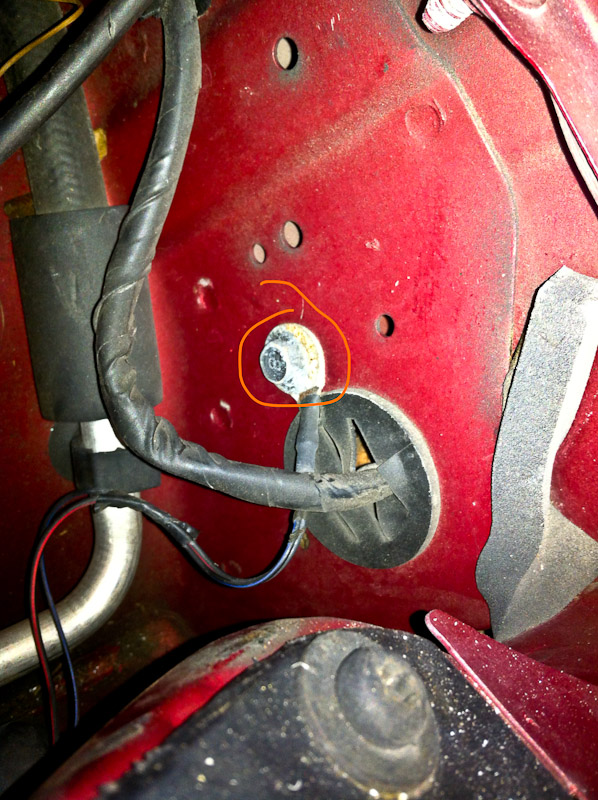
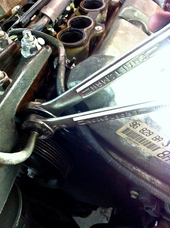
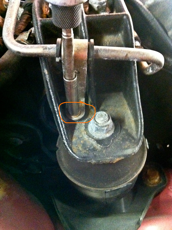
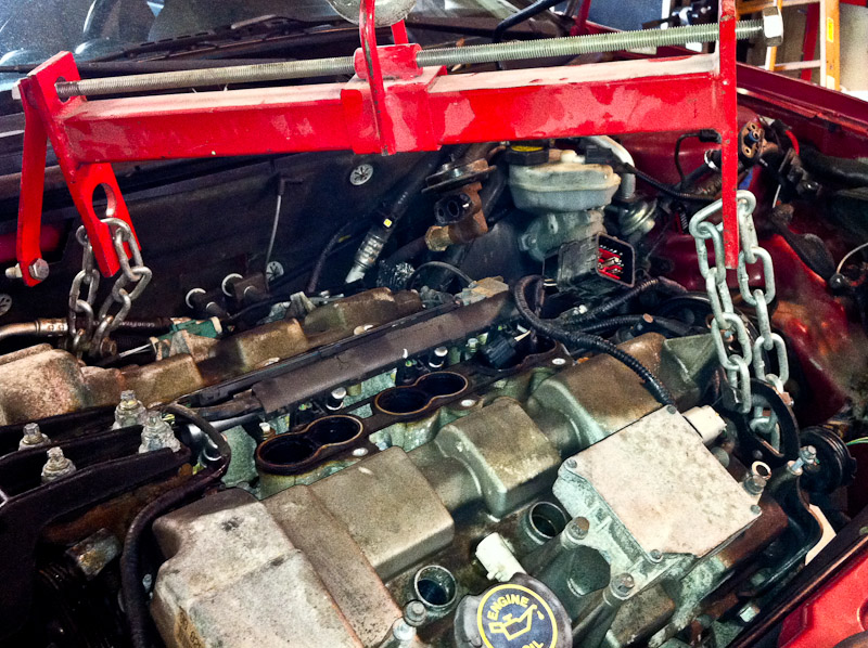
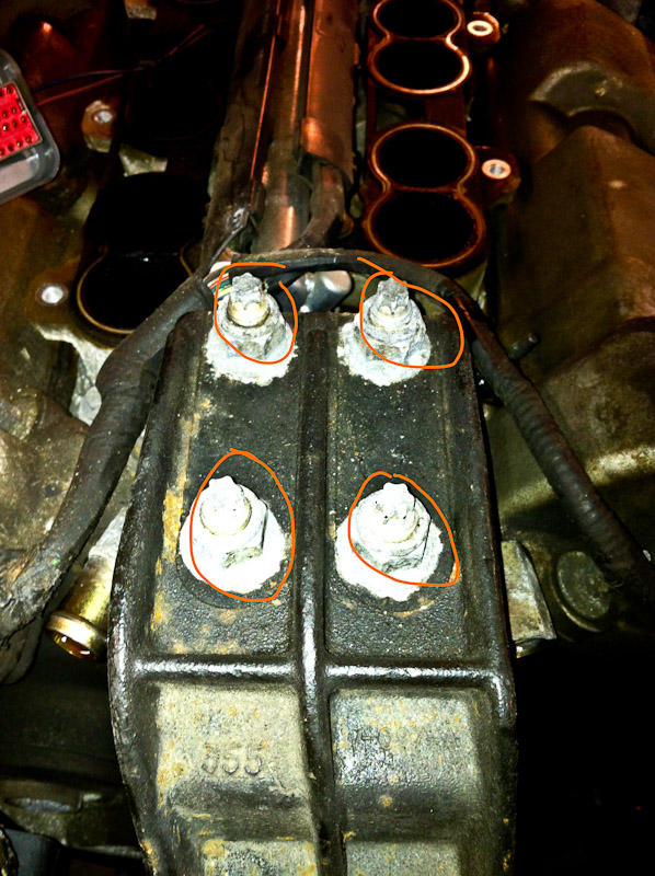
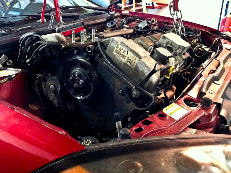
16. Remove coil pack from rear of motor - four 7mm bolts.
It was already removed from this car, but I've circled the bolts. *The 01/02 will only have 3 bolts*
![Image]()
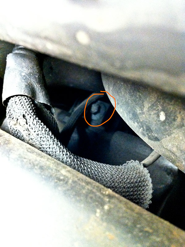
17. Remove rear three plug wires and remove coil pack/wire assembly.
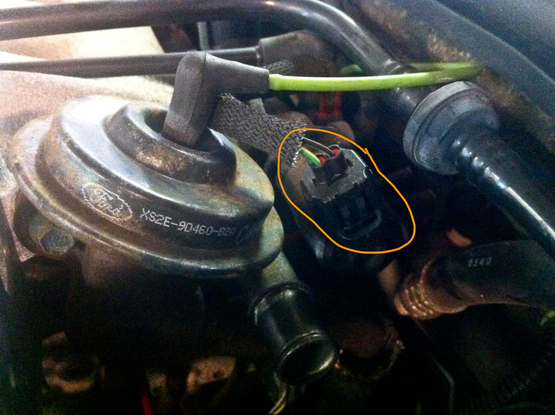
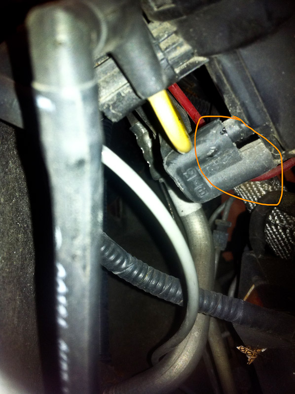
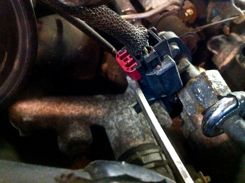
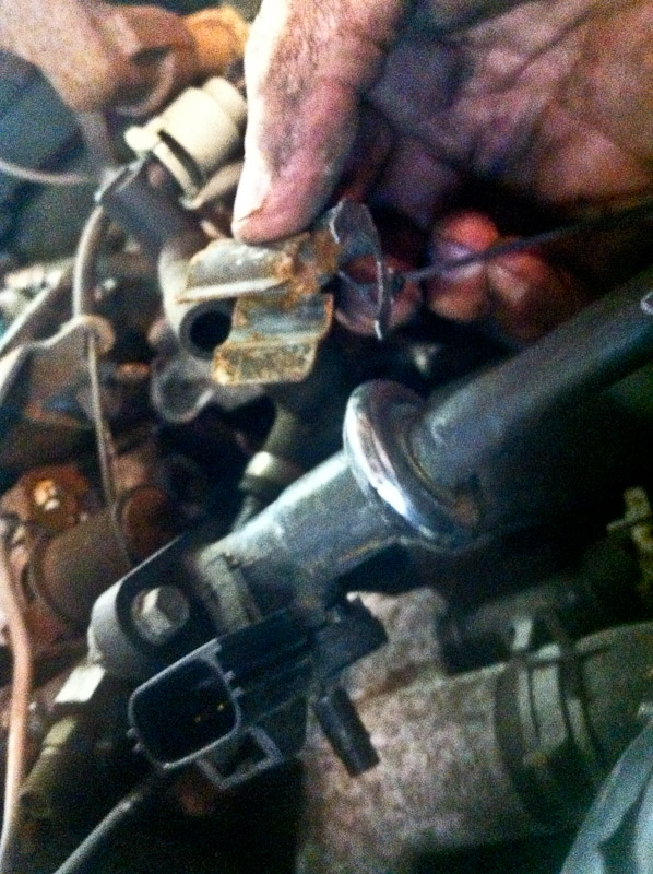
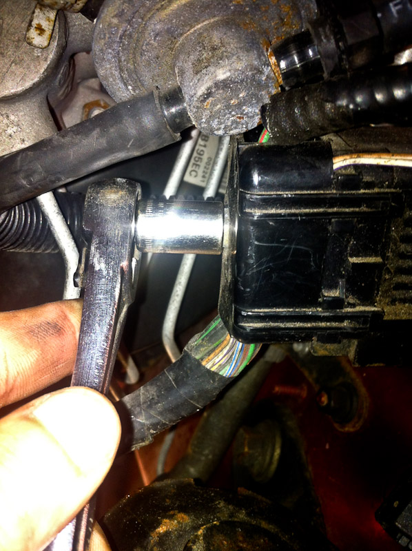
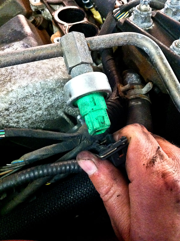
18. Unplug MAF sensor and IAT sensor.
![Image]()
![Image]()
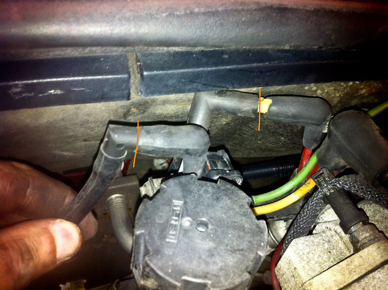
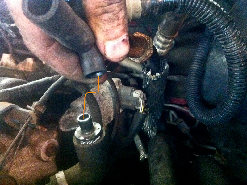
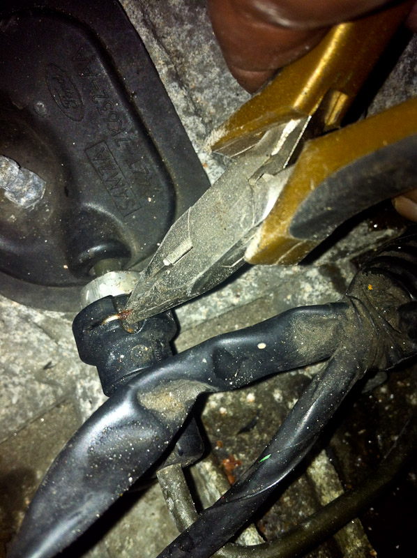
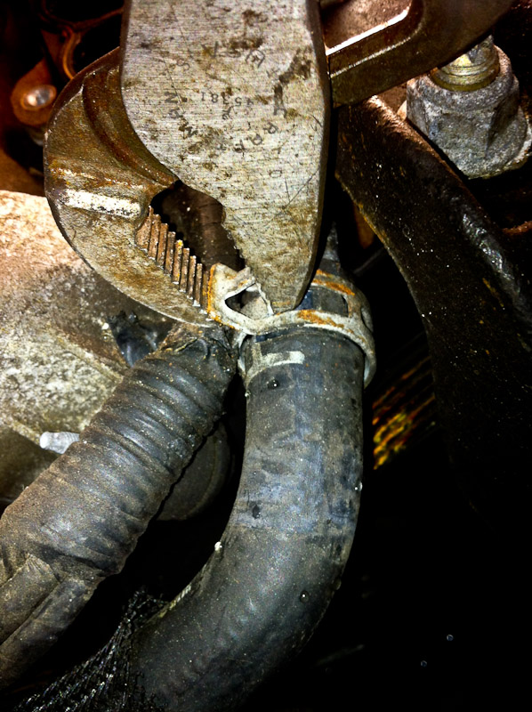
19. Remove front and rear breathers from cam covers.
![Image]()
![Image]()
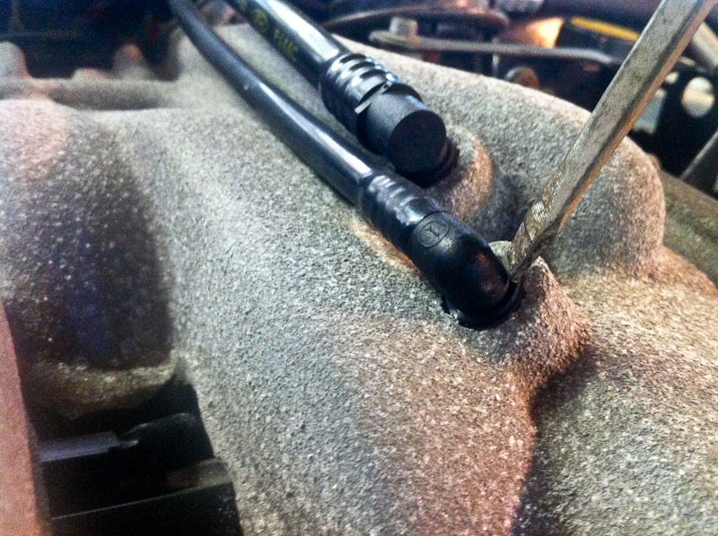
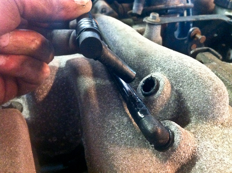
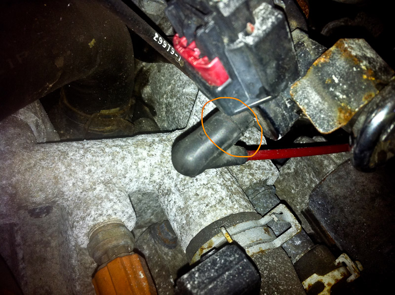
20. Remove IACV feed hose from UIM - screwdriver.
![Image]()
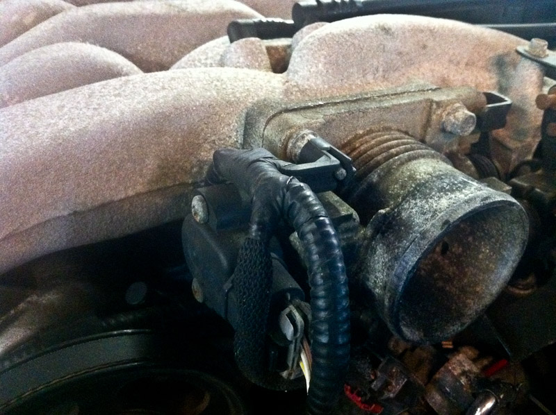
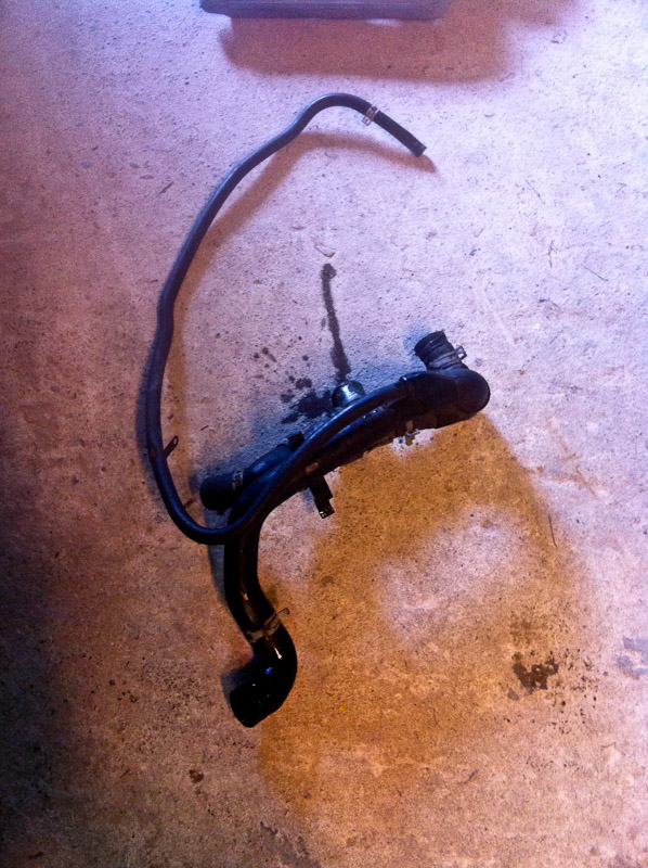
21. Remove accordion tube from TB - screwdriver.
![Image]()
22. Pull back on accordion tube and lift complete airbox assembly out of the car.
![Image]()
![Image]()
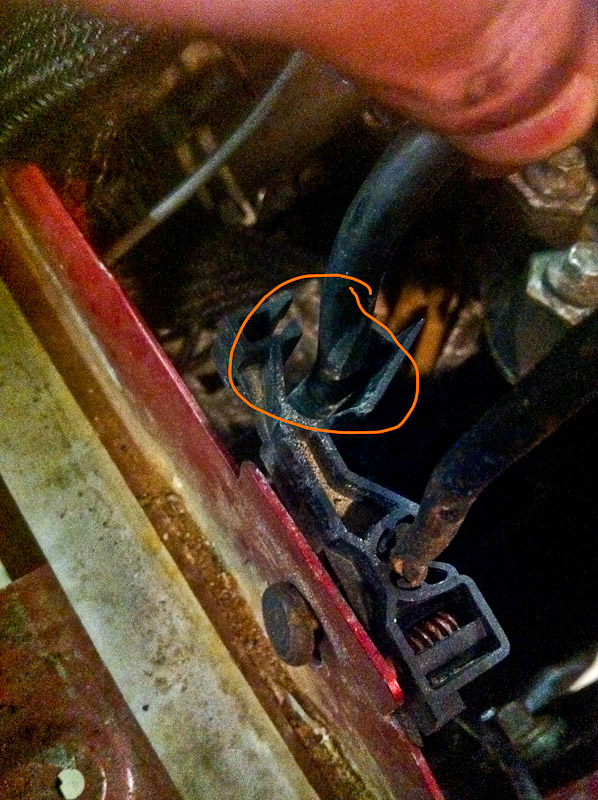
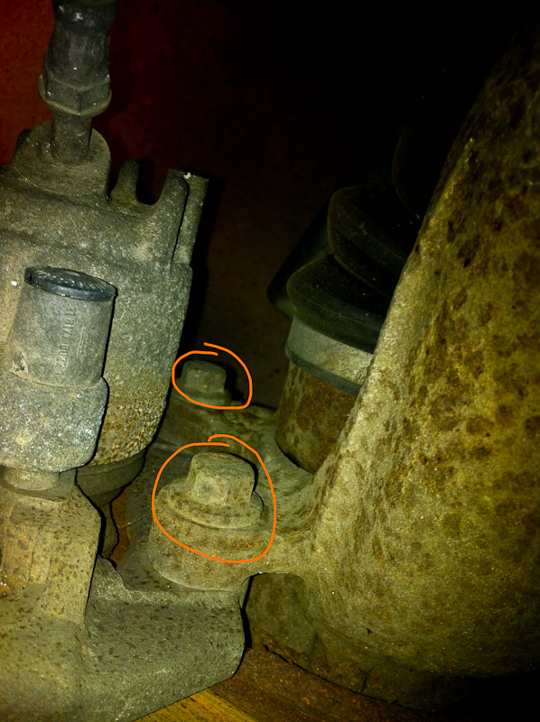
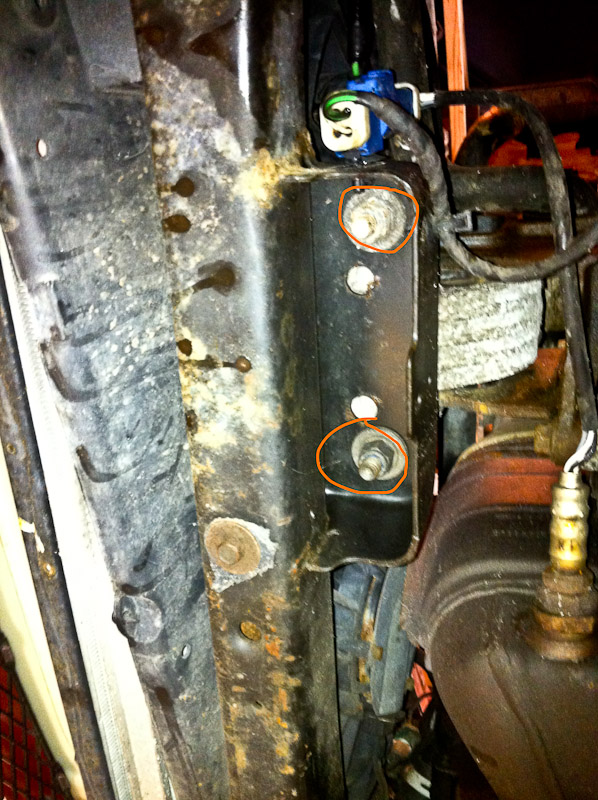
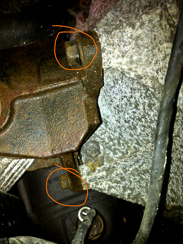
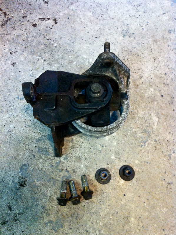
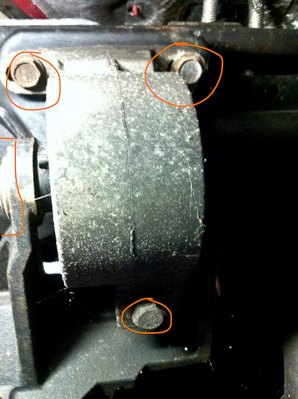
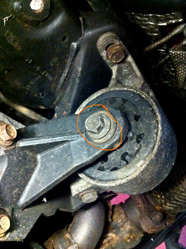
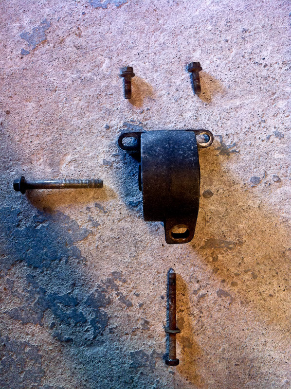
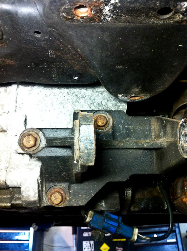
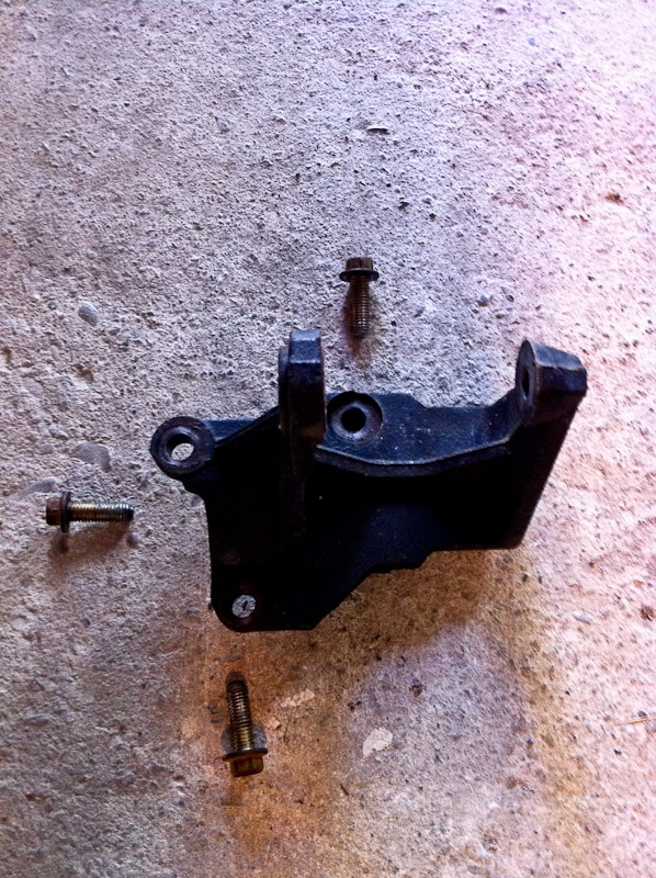
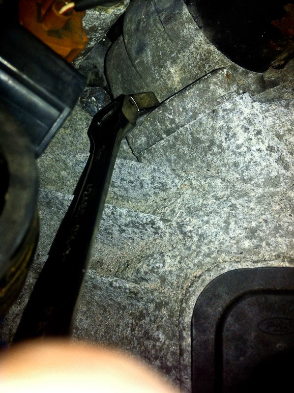
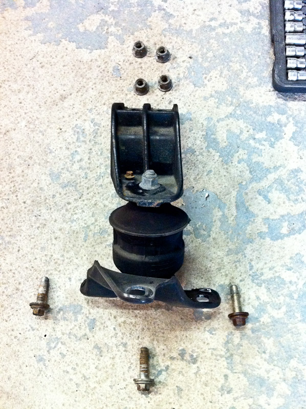
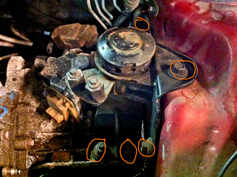
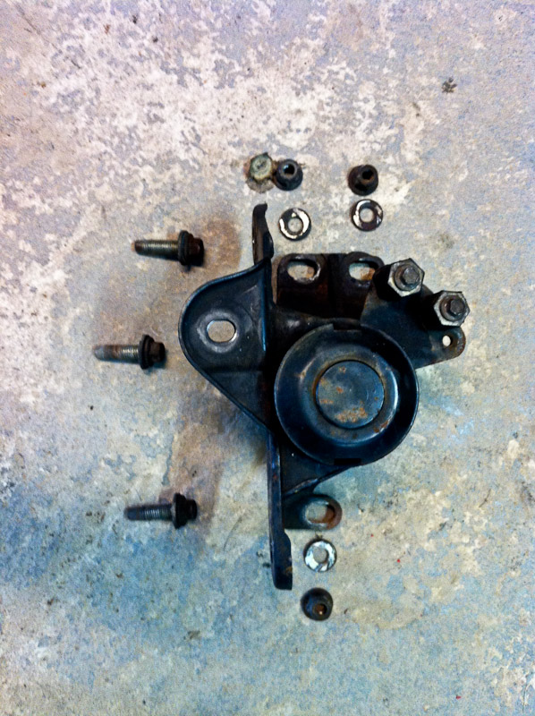
23. Remove airbox support from trans mount - two 10mm bolts.
![Image]()
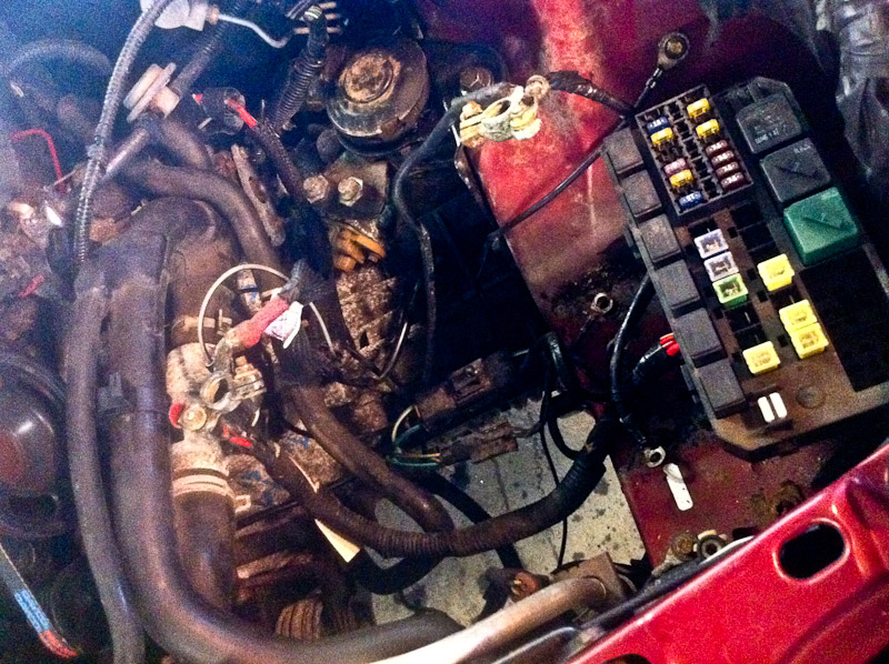
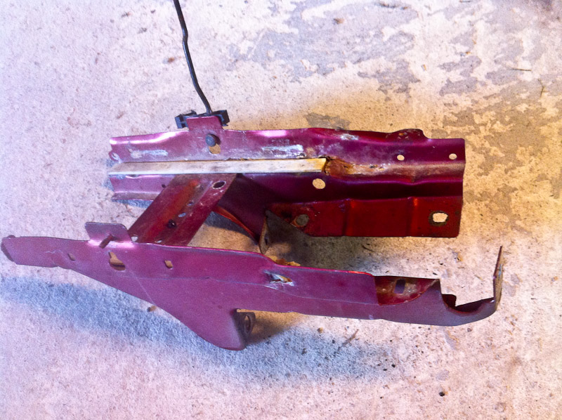
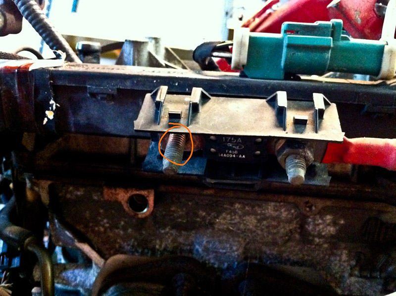
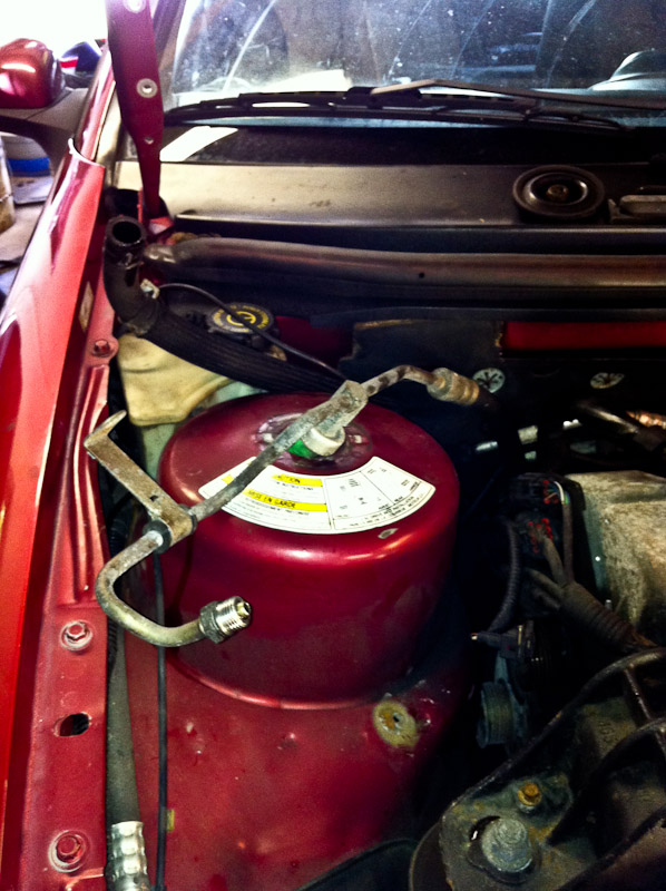
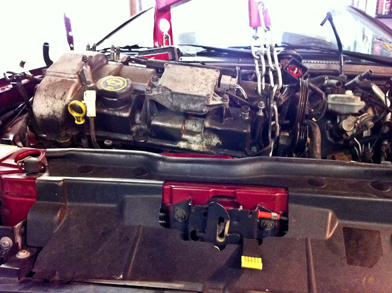
24. Unbolt fuse box from battery tray - one 8mm bolt. Pull up and slide back
![Image]()
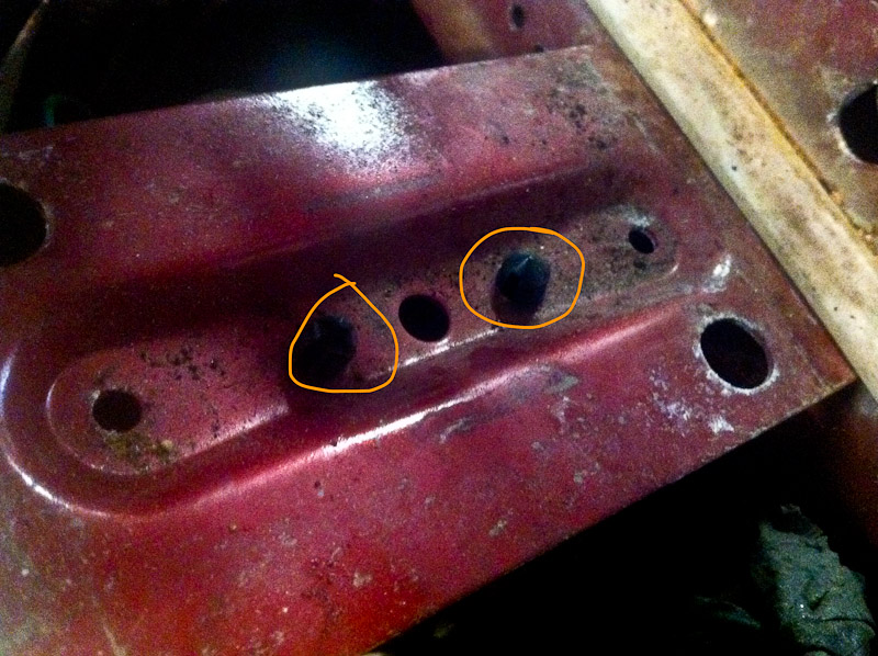
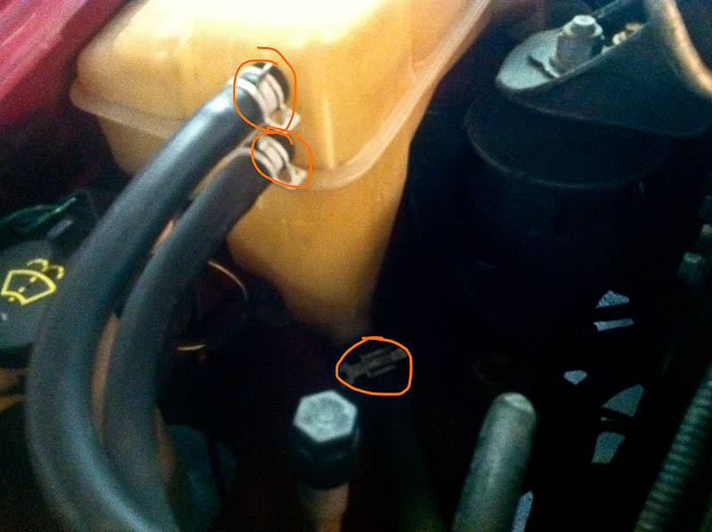
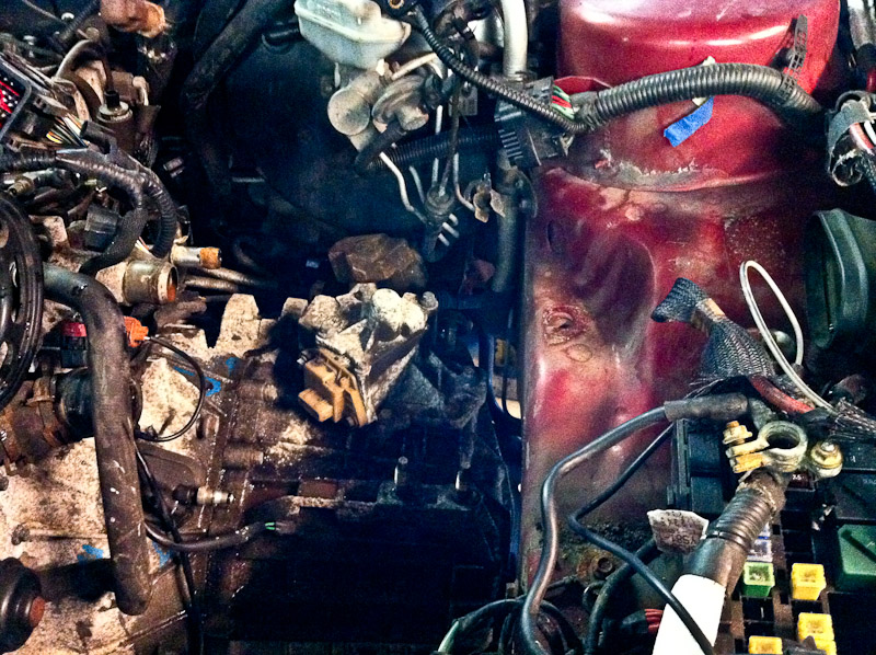
25. Remove all seven 10mm battery tray bolts. Note how wiring is ran and where grounds are.
![Image]()
![Image]()
![Image]()
![Image]()
![Image]()
*Everyone does it different...this is how I do it. This thread isn't going to turn into a pissing match of which way works better, but if you have experience doing something another way, feel free to post up the option*
This particular pull was on a 2000 Cougar 2.5 MTX V6 that was bone stock, It was a returnless fuel system, but I'll try to note the differences if you pulling a return style engine.
The engine in an 01/02 will be returnless like this one, but will have some other slight differences. I'll try to note those as well.
Have a clean garage, organized tools, oil dry, lot's of PB Blaster, three separate containers (for oil, trans fluid, and antifreeze), and a supply of good beer, and this will go quite smoothly.
1. Jack up car, support on jackstands (I put them on the subframe, just ahead of the rear subframe bolts. Remove the splash shield from the bumper (f it's still there), and remove the serpentine belt.
2. Remove the hood – four 10mm bolts, ground is one 8mm, pull washer hose.


3. Drain oil – 15mm

4. Drain trans fluid – 8mm allen


5. Drain coolant – Place a large bucket under the car, use a short flat-head screwdriver. Have some oil dry handy, and of course be careful of animals getting into the antifreeze, as it's poisonous.


6. Remove front wheels. Place under the car for extra safety.


7. Spray PB blaster on y-pipe bolts/engine mounts, suspension bolts.
8. Remove battery hold-down - holder two 10mm nuts.
9. Remove battery cables and battery.


10. Remove cover under battery.

11. Spray battery tray bolts with PB Blaster - 7 bolts.
12. Remove Duratec cover - three 7mm bolts.

13. Remove IMRC temporarily to access spark plug boots - three 10mm bolts.

14. Pull out plug wires from front valve cover

15. Replace IMRC.
16. Remove coil pack from rear of motor - four 7mm bolts.
It was already removed from this car, but I've circled the bolts. *The 01/02 will only have 3 bolts*

17. Remove rear three plug wires and remove coil pack/wire assembly.
18. Unplug MAF sensor and IAT sensor.


19. Remove front and rear breathers from cam covers.

20. Remove IACV feed hose from UIM - screwdriver.

21. Remove accordion tube from TB - screwdriver.

22. Pull back on accordion tube and lift complete airbox assembly out of the car.


23. Remove airbox support from trans mount - two 10mm bolts.

24. Unbolt fuse box from battery tray - one 8mm bolt. Pull up and slide back

25. Remove all seven 10mm battery tray bolts. Note how wiring is ran and where grounds are.


") Removing my first cougar motor today(finish tomorrow i think) for a friend and this has been great! Just have to figure out what things get disconnected for an auto tranny too.
Removing my first cougar motor today(finish tomorrow i think) for a friend and this has been great! Just have to figure out what things get disconnected for an auto tranny too.